Testing O2 Sensor
2017 Update Class
Testing O2 Sensor
Some of the Images are from your Smog License Update Class manual by AGT Training
I know coming from work and setting in a class lecture can be hard but I appreciate your effort.
This is the lecture from class repeated just encase you came in late or dose off LOL.
Testing O2 Sensor: Voltage Range
Testing O2 Sensor
The O2 sensor voltage should range from 100mv to 900mv with an average of 450mv the PCM "Power Train Control Module" will consider this a proper operating range.
The best way to test an O2 sensor is with a lab scope, not a scan tool or DVOM "Digital Volt Ohmmeter." But if you don't have a Lab Scope I would use a DVOM; next would be a Scan Tool.
You would be right if you are thinking a scan tool has a slow update rate, but the speed could increase with your help. If you would like to make the scan tool faster, you need to customize the scan tool with fewer parameters on the data screen to process.
Decreasing the Parameter data the scan tool is processing will increase the speed so the data would process faster.
Now if you have a graph on your scan tool, it would be very helpful in graphing signals, and comparing them to one and another.
Testing O2 Sensor: Graphing the Signal

Imagine by AGT SMOG UPDATE TRAINING MANUAL
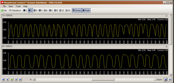
Graphing signals and comparing them to each other is a great exercise when looking at O2 sensor signals. You can compare O2 Sensor Bank 1 Sensor 1 to O2 Sensor Bank 2 Sensor 1.
Once I had a vehicle with a DTC "Diagnostic Trouble Code" for an O2 sensor on bank one front sensor. So I graph two signals only Bank 1 and Bank 2 front sensors.
The proper procedure would be to get propane or some flammable chemical to introduce it into the introduction system.
When you add the propane both front sensors should rise in this case the bank which had the DTC didn't even move the other bank move towards 1000mv, which indicates a dead sensor or wiring problem on the bank that didn't move.
But I was lazy; I just rev the throttle two or three times the bank that was working move up the bank that was generating the DTC did not.
I replace the sensor and recheck the circuit now everything looks O.K.
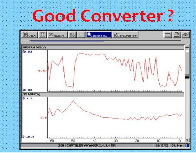
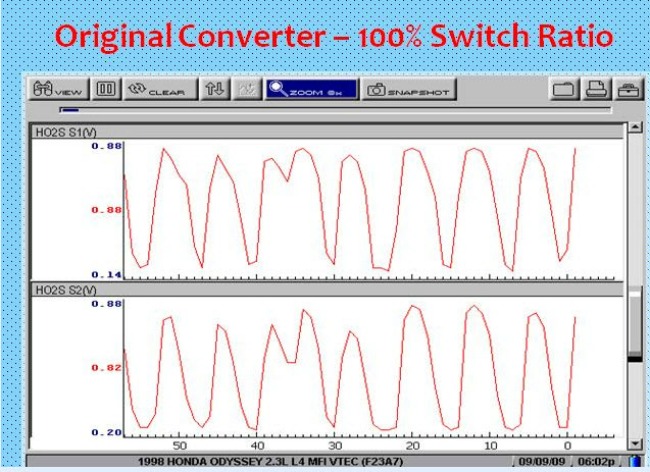
How about checking the catalytic converter on the scan tool, one way is to graph Bank One Sensor 1 to Bank One Sensor 2, in other words, graph the front and rear sensor for comparison and catalytic converter operation.

Keep in mind what you are looking for is the front O2 sensor to have more activity than the rear. If both sensors look like each other, you could have a defective catalytic converter.
You can use bank two front and rear sensor also for this test.
A lazy O2 sensor can also give you a false P0420 Catalytic Converter code, so confirm the O2 sensor operation.
Now don't get me wrong it's hard to see a lazy O2 sensor not switching under 100ms on a scan tool.
Testing O2 Sensor: Lazy O2 signal and Bad Catalyst

In this situation you will need a lab scope, one thing you should consider, a lazy O2 sensor can cause a TWC "Three Way Catalytic Converter" not to work efficiently and create high emissions.
I have also seen when worn plugs or lazy O2 sensor causing a false P0420 or P0430 code.
A Three-way catalytic converter needs the O2 sensor to switch quickly to reduce all three emissions, HC "Hydrocarbons" CO "Carbon Monoxide" and Nox "Oxides of Nitrogen."
Testing O2 Sensor: O2 Sensor Heater
Now there are times when you will get a code for O2 sensor heater.
I would usually check for power and ground going to the heater circuit for the O2 sensor. Then I would Ohm the heater portion of the sensor and compare it to the specifications if you can find the specifications in a repair manual for that vehicle.
Here is another trick, it's also mentioned in your AGT training manual from the 2017 smog update class.
Use your scan tool and graph two sensors any two but one has to be the one causing the code.
It doesn't matter if its two front sensors or one front and one rear as long as the one causing the code is being graphed.
If its two front its better, but the rear will work but the activity will not be the same.
Start a cold car up and watch how long it takes the sensor the one that set the code to come alive compared to the one that didn't set the code.
All sensors should activate about the same time, if not the heater portion of the sensor isn't functional.
Now there are some things that's hard to see on a scan tool but with an O2 sensor, there are things you can see easily.
Here are some:
- A nonoperative O2 sensor quickly hit the gas pedal to the floor and release; the O2 sensor should rise towards 900mv if it's a zirconia sensor.
If it doesn't the sensor or wiring are at fault.
- An O2 sensor should cycle from 100mv to 900mv at 2000RPMs consistently. Try not to check an O2 sensor at idle it can give you false readings.
- The one thing you can not check is how fast an O2 sensor is switching. Usually, you would lean to rich in under 100ms and for that test you will need a Lab Scope / DSO "Digital Storage Oscilloscope" aka Lab Scope.
additional Information on Catalytic Converter Click Here
I appreciate you for reading my material if you like the information do me a big favor and click the LIKE BUTTON if you are on Facebook.
CLASS SCHEDULES
Emission Control 1:
B.A.R. Smog Check
Inspector Level 1
(Inspector "Smog" License):
Engine Fundamentals
8am - 12:15 pm
Summer Class
7/5/2022 -8/5/2022
Class # 799065
Emission Control 2:
B.A.R. Smog Check
Inspector Level 2
(Inspector "Smog" License):
Rules and Regulations
8am - 12:15 pm
Summer Classes
7/5/2022 - 8/5/2022
Class # 799067
Engine Performance 1:
8am - 12: 15 pm
Date: TBD
Class # 799069
Engine Performance 2:
B.A.R. Specified Diagnostic
and Repair Training
(Repair "Smog" License)
Time: TBD
Date: TBD
Class # 799071
Emission Control 1
(Inspector "Smog" License):
5:00pm - 8:45 pm
Date: TBD
Class # 799065
Emission Control 2:
(Inspector "Smog" License):
5:00pm - 8:45 pm
Date: TBD
Class # 799065
Exhaust Emissions (Update Class):
5:30 pm - 8:45 pm
Tuesday nights:
Dates: coming soon
Class # 796070