2017 Smog Update Class: Comprehensive Component Monitor
Some of the Images are from your Smog License Update Class manual by AGT Training
I know coming from work and setting in a class lecture can be hard but I appreciate your effort.
This is the lecture from class repeated just encase you came in late or dose off LOL.
Smog Update Class: Comprehensive Component Monitor
Understanding an OBD 2 monitor can be little difficult to comprehend, but it is only one device checking another. Cause and effect, as I have been teaching in my classes thru the years.
When I explain monitor operation, I use my two kids as the example, If you have kids you have probably told he or her to go clean their room. They walk in their room and close the door.
How do you know if they are cleaning their room, you gave out the command but is the command being carried out.
Smog Update Class: Comprehensive Component Monitor - Operation
So you send in the little monitor the younger sibling into the room, then they will report back to you yes they are cleaning the room "pass" or no they are on their cell phone talking to their friends "fail."
An OBD2 monitor is similar, the PCM "Power Train Control Module" will monitor each induvial emission component for proper operation.
On slide three pg 1-7 from the AGT smog update class book they are talking about a monitor, something very simple one of the first monitors before 1996.
Smog Update Class: Comprehensive Component Monitor - EGR Temp. Sensor
The EGR Temperature sensor, this sensor has been on vehicles for many years before it was mandated in 1996.
This system uses an EGR NTC "Negative Temperature Coefficient" sensor. The sensor will change voltage base off the temperature from the exhaust flow.
Understand the voltage will only change once the hot exhaust passes through the EGR passage passing the temperature sensor.
So the change in voltage indicates the EGR valve is functional when the PCM command was given out.
Once the PCM gives out the command for the EGR to function and the correct, enable criteria has been met, the PCM will run the monitor.
I would like you to understand this, when I say the PCM is running a monitor, it just means the PCM is testing that circuit.
Once the PCM see's its command is being carried out and the voltage reaches a certain threshold the PCM will consider it a pass if the voltage doesn't change the circuit fails.
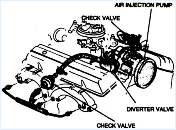
The slide also shows you if the PCM is testing the AIS or "Air In Injection System" it will watch the O2 sensor for a shift in the voltage when the A.I.S. is commanded on.
Again this change in voltage indicates the A.I.S. is functional.
Smog Update Class: Comprehensive Component Monitor - A.I.S
CMP "cam position sensor" and CKP "crank position sensor" relationship are monitor against each other for timing performance.
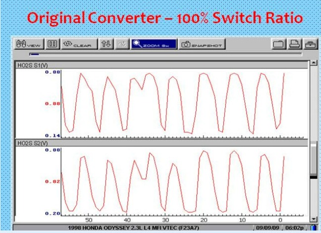
The most command monitor and the easiest to understand in my opinion is the catalytic converter monitor. The PCM will compare the upstream and downstream O2 sensor for catalyst operation.
If the catalytic converter is absorbing the O2, the rear O2 sensor will confirm a proper operating catalyst with very little activity.
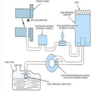
Slide 4 from the Smog Update Class and AGT Book is discussing the EVAP monitor and the OBD II system.
Smog Update Class: Comprehensive Component Monitor - Defective Catalytic Converter
The Evap monitor is looking for a leak within the system, is the purge flowing. Is there an open or short within the purge or vent valve.
Something to remember the CCM "Comprehensive Component Monitor" check for opens, shorts, grounds, functionality, and rationality.
On the evap monitor if the purge valve or vent valve has an open or short in the circuit or component the PCM will set a DTC "Diagnostic Trouble Code".
If there is no vapor flow or if there is a leak within the system again the PCM will set a DTC.
As you can see the Evap Monitor can set several different codes within the evap system and trigger a DTC and the check engine light each failure.
When trying to diagnosis, an Evap system a bi-directional scan tool and a smog machine is crucial.
Let's talk about a common code PO420 low catalyst efficiency as we explain earlier the catalyst monitor will fail this component if the rear O2 sensor has too much activity.
But remember just because a monitor fails a certain emission component does not mean that component is defective. This is why the circuit needs diagnoses without replacing the part first.
For an example a lazy O2 sensor will set a PO420, I remember when I was on the phone ordering a cat for my car when I realize I never check the O2 sensor.
I then had the students perform a performance test on the o2 sensors and they both fail, replace the O2 sensor's "no cat" the vehicle pass the smog test.
Slide 6 is showing the relation between monitors and some emission components.
For example, the catalytic converter monitor relies on the O2 sensor's so it only makes since to confirm that the sensors are functional and operating within design parameters.
Smog Update Class: Comprehensive Component Monitor - Confirm O2 sensor operation before replacing catalytic converter
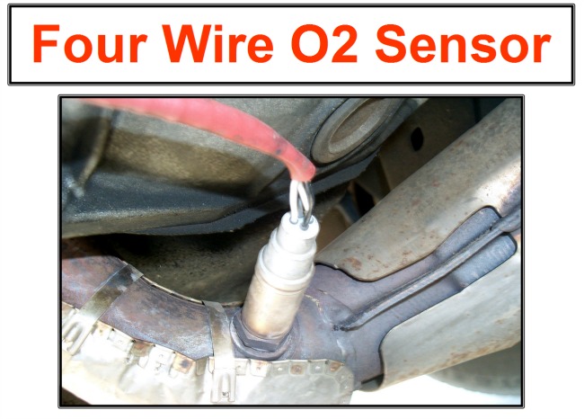
Remember a monitor in some cases will need a sensor to compare against another sensor for testing a component.
The CCM is continuously looking at different inputs and outputs and examining that they are within the desired range.
Let's talk about two monitors Non-Continuous and Continuous Monitors; non continuous monitors would have an enable criteria before that particular monitor runs. Continuous monitors will run all of the time; they are always testing for a fault.
Smog Update Class: Comprehensive Component Monitor - Drive Cycle
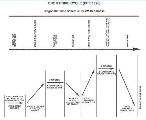
Like OBDI, OBDII will watch for an out of range signal from a sensor as in slide 7, the operating voltage range is from.5v to 4.5v but if the sensor reads below or over those parameters for example 0.0 volts or 5.0 volts a code will be set.
This was the same concept in OBDI but the difference with OBD II, OBD II checks for rationality.
Rationality is the signal logical If you are driving down the street at 55MPG but the TPS is indicating you are at idle to the PCM this not is logical and will set a DTC.
Also, CCM monitors will check for the proper output voltage on a circuit, does the voltage change when commanded on or off, the PCM is looking for the proper voltage response.
On slide eight from the class the AGT Update Book it's showing you a quick check to see if the vehicle has a worn or stuck throttle plate. The manual state's KOEO read the minimum throttle voltage, and then again at idle.
If the throttle shaft could be worn, the throttle plate will often stick only when vacuum is pulling on it at idle. AGT states if the there is more than a few mv difference in the signal between KOEO and KOER it indicates a worn or very dirty throttle body.
I would be careful with that statement, practice on known go cars, I have seen actuators come on and change the voltage readings.
Smog Update Class: Comprehensive Component Monitor - TPS DATA
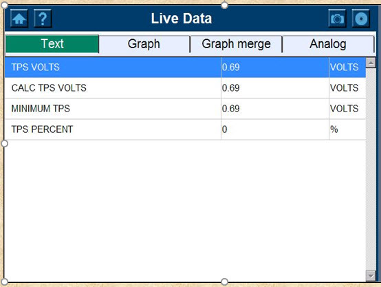
IMAGINE BY AGT TRAINING
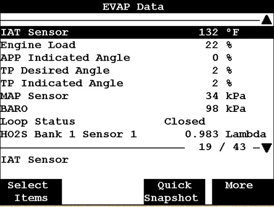
On slide nine it talks about a MAP / BARO sensor, now this is very important input. I remember when a Ford Tempo kick my ass for a day or two because I didn't pay attention to the BARO reading.
KOEO the PCM reads the BARO reading either from the MAP sensor if there isn’t a separate BARO sensor or from the BARO sensor its self. KOEO the manifold conditions are the same as atmospheric pressure.
PCM uses this input for fuel pulse width calculations, so if this reading is off the whole fuel Mapping table will be out of calibration.
As the CCM is looking for a circuit rationality, you to can do the same by using your scan tool data and looking or comparing sensors voltage against each other.
Smog Update Class: Comprehensive Component Monitor - MAP / BARO Data
Slide 10 is showing you how to compare the ECT "Engine Coolant Temperature" sensor against the IAT "Intake Air Temperature" sensor.
When the vehicle is cold the ECT and IAT should be within 10% of each other; I had seen when cars had been towed into the shop when these readings were off.
When it comes down to diagnosing a CCM code one critical thing you need to understand is knowing how to use your scan tool along with reading a wiring diagram.
Smog Update Class: Comprehensive Component Monitor - ECT IAT PID
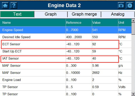
IMAGINE BY AGT TRAINING
Reading reference voltage and understanding grounds is critical for voltage inputs and switching circuits.
There is another function that the CCM is monitoring which is functionality, is the part or device working.
This is when a good bi-directional scan tool will help you see if a component is functioning. For example, the IAC "Idle Air Control" motor can be tested for an idle speed out of range code.
Smog Update Class: Comprehensive Component Monitor CCM - Checks for opens shorts grounds and rationality
Now, this may not catch a glitch, but it will assist you to see if the component is functional.
As I said earlier the CCM "Comprehensive Component Monitor" is continuously checking for opens, shorts, grounds and rationality. Which means its testing certain circuits and their actual performance.
CLASS SCHEDULES
Emission Control 1:
B.A.R. Smog Check
Inspector Level 1
(Inspector "Smog" License):
Engine Fundamentals
8am - 12:15 pm
Summer Class
7/5/2022 -8/5/2022
Class # 799065
Emission Control 2:
B.A.R. Smog Check
Inspector Level 2
(Inspector "Smog" License):
Rules and Regulations
8am - 12:15 pm
Summer Classes
7/5/2022 - 8/5/2022
Class # 799067
Engine Performance 1:
8am - 12: 15 pm
Date: TBD
Class # 799069
Engine Performance 2:
B.A.R. Specified Diagnostic
and Repair Training
(Repair "Smog" License)
Time: TBD
Date: TBD
Class # 799071
Emission Control 1
(Inspector "Smog" License):
5:00pm - 8:45 pm
Date: TBD
Class # 799065
Emission Control 2:
(Inspector "Smog" License):
5:00pm - 8:45 pm
Date: TBD
Class # 799065
Exhaust Emissions (Update Class):
5:30 pm - 8:45 pm
Tuesday nights:
Dates: coming soon
Class # 796070